As a supplier of current transformers, I often encounter clients who are curious about the principle behind these essential electrical devices. In this blog post, I’ll delve into the fundamental principles of current transformers, their working mechanisms, and their significance in various applications. Current Transformer
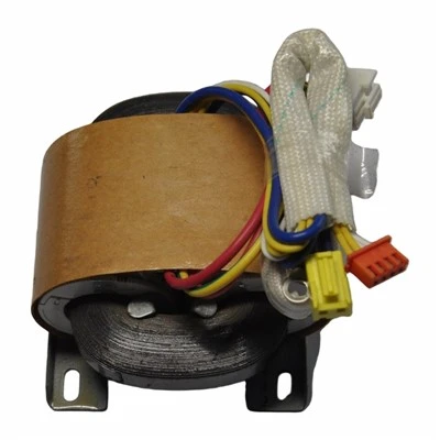
The Basics of Current Transformers
A current transformer, commonly referred to as a CT, is an instrument transformer designed to measure high electrical currents by providing a reduced secondary current that is proportional to the primary current. It is a crucial component in electrical power systems, used for metering, protection, and control purposes. The primary function of a current transformer is to step down the high current in the primary circuit to a lower, measurable value in the secondary circuit while maintaining a known ratio between the two currents.
The Working Principle
The working principle of a current transformer is based on the phenomenon of electromagnetic induction, which was discovered by Michael Faraday in the early 19th century. According to Faraday’s law of electromagnetic induction, a changing magnetic field induces an electromotive force (EMF) in a conductor. In the case of a current transformer, the primary winding is connected in series with the high-current circuit, and the secondary winding is connected to a measuring or protective device.
When an alternating current flows through the primary winding, it creates a magnetic field around the winding. This magnetic field is proportional to the magnitude of the primary current. The secondary winding, which is wound around the same magnetic core as the primary winding, is exposed to this magnetic field. As the magnetic field changes due to the alternating current in the primary winding, an EMF is induced in the secondary winding according to Faraday’s law.
The induced EMF in the secondary winding causes a current to flow in the secondary circuit. The ratio of the primary current to the secondary current is determined by the turns ratio of the transformer, which is the ratio of the number of turns in the primary winding to the number of turns in the secondary winding. For example, if a current transformer has a turns ratio of 100:1, a primary current of 100 amperes will produce a secondary current of 1 ampere.
Construction of a Current Transformer
A current transformer typically consists of a magnetic core, primary winding, secondary winding, and insulation. The magnetic core is made of a high-permeability material, such as silicon steel, to provide a low-reluctance path for the magnetic field. The primary winding is usually a single turn or a few turns of heavy-gauge conductor, while the secondary winding consists of many turns of fine-gauge conductor.
The primary winding is connected in series with the high-current circuit, and the secondary winding is connected to a measuring or protective device, such as a ammeter, wattmeter, or relay. The insulation between the primary and secondary windings is designed to withstand the high voltage and current levels in the primary circuit.
Types of Current Transformers
There are several types of current transformers, each designed for specific applications. The most common types include:
- Wound-Type Current Transformers: These are the most traditional type of current transformers, where the primary and secondary windings are wound on a common magnetic core. They are suitable for a wide range of applications and can be used to measure high currents.
- Bar-Type Current Transformers: In bar-type current transformers, the primary winding is a single straight bar of conductor that passes through the center of the transformer core. They are typically used for high-current applications and are easy to install.
- Split-Core Current Transformers: Split-core current transformers are designed for easy installation and removal without the need to disconnect the primary circuit. They consist of two halves of a magnetic core that can be separated and then clamped around the primary conductor.
- Clamp-On Current Transformers: Clamp-on current transformers, also known as current clamps, are a type of split-core current transformer that can be easily clamped around a conductor without the need for any wiring. They are commonly used for portable current measurement applications.
Applications of Current Transformers
Current transformers are widely used in various electrical power systems and applications, including:
- Metering: Current transformers are used in electrical meters to measure the amount of electrical energy consumed by a customer. They provide a reduced secondary current that is proportional to the primary current, which can be accurately measured by the meter.
- Protection: In electrical power systems, current transformers are used in protective relays to detect abnormal current conditions, such as overcurrent, short circuits, and ground faults. The secondary current from the current transformer is used to operate the relay, which can then trip the circuit breaker to isolate the faulty section of the system.
- Control: Current transformers are also used in control circuits to monitor the current in a circuit and provide feedback to a control device, such as a motor controller or a power supply. The control device can then adjust the operation of the circuit based on the measured current.
Importance of Current Transformers in Electrical Systems
Current transformers play a crucial role in the safe and efficient operation of electrical power systems. They provide a means of measuring high currents accurately and safely, which is essential for metering, protection, and control purposes. Without current transformers, it would be difficult to measure and monitor the current in high-voltage and high-current circuits, which could lead to overloading, equipment damage, and electrical accidents.
In addition, current transformers help to isolate the measuring and protective devices from the high-voltage and high-current primary circuit, which provides an additional layer of safety for the operators and the equipment. They also allow for the use of standard measuring and protective devices, which are designed to operate at lower current levels.
Factors Affecting the Performance of Current Transformers
The performance of a current transformer can be affected by several factors, including:
- Burden: The burden is the impedance of the secondary circuit, including the measuring or protective device and the connecting wires. A high burden can cause the secondary current to deviate from the ideal value, which can affect the accuracy of the measurement or the operation of the protective relay.
- Magnetic Saturation: Magnetic saturation occurs when the magnetic core of the current transformer becomes fully magnetized and can no longer support an increase in the magnetic field. This can cause the secondary current to distort and deviate from the ideal value, which can affect the accuracy of the measurement or the operation of the protective relay.
- Frequency: The performance of a current transformer is also affected by the frequency of the alternating current. Most current transformers are designed to operate at a specific frequency, typically 50 or 60 Hz. Operating a current transformer at a different frequency can cause the secondary current to deviate from the ideal value, which can affect the accuracy of the measurement or the operation of the protective relay.
- Temperature: The performance of a current transformer is also affected by the temperature. High temperatures can cause the resistance of the windings to increase, which can affect the accuracy of the measurement or the operation of the protective relay.
Conclusion
In conclusion, the principle of a current transformer is based on the phenomenon of electromagnetic induction, which allows for the measurement of high electrical currents by providing a reduced secondary current that is proportional to the primary current. Current transformers are essential components in electrical power systems, used for metering, protection, and control purposes. They play a crucial role in the safe and efficient operation of electrical power systems and help to isolate the measuring and protective devices from the high-voltage and high-current primary circuit.
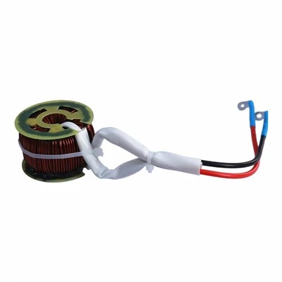
As a supplier of current transformers, we understand the importance of providing high-quality products that meet the needs of our customers. Our current transformers are designed and manufactured to the highest standards, using the latest technologies and materials. We offer a wide range of current transformers to suit various applications, including wound-type, bar-type, split-core, and clamp-on current transformers.
Flyback Transformer If you are in need of current transformers for your electrical power system, we invite you to contact us to discuss your requirements. Our team of experts will be happy to assist you in selecting the right current transformers for your application and provide you with a competitive quote. We look forward to working with you to meet your current transformer needs.
References
- Electric Machinery, 7th Edition, Stephen J. Chapman
- Power System Analysis and Design, 6th Edition, J. Duncan Glover, Mulukutla S. Sarma, Thomas J. Overbye
- Electrical Power Systems: Design and Analysis, 2nd Edition, Turan Gonen
Dongguan Hensiron Electric Co., Ltd.
As one of the most professional current transformer suppliers in China, we have world-leading production equipment and strong manufacturing capabilities. Please feel free to buy high quality current transformer made in China here from our factory. Customized orders are welcome.
Address: Building 4, Xinxing Industrial Zone, Wangao Road, Wanjiang Street, Dongguan City, China
E-mail: jessica@dghensiron.com
WebSite: https://www.dghensiron.com/
